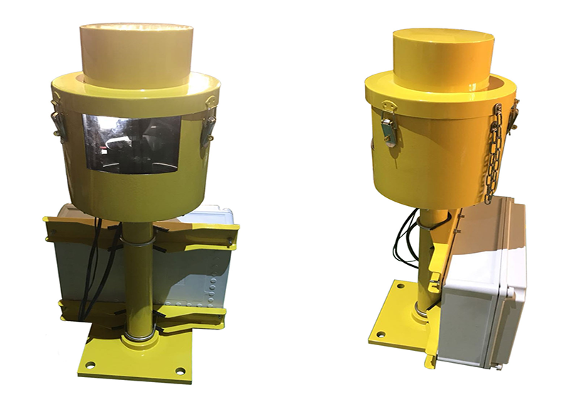
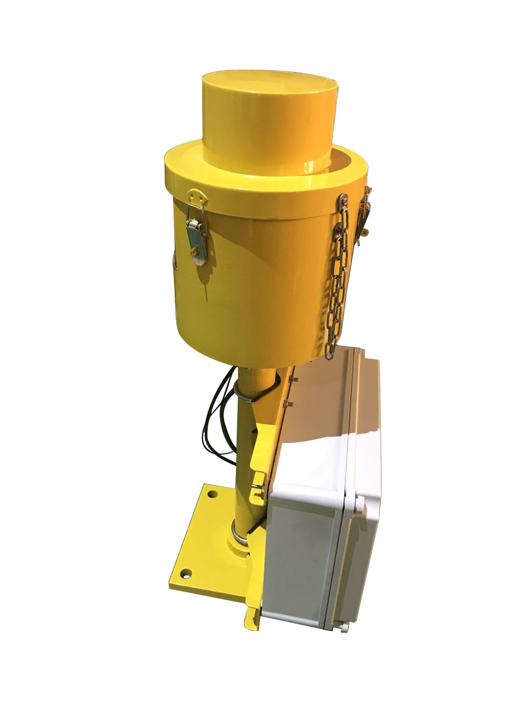
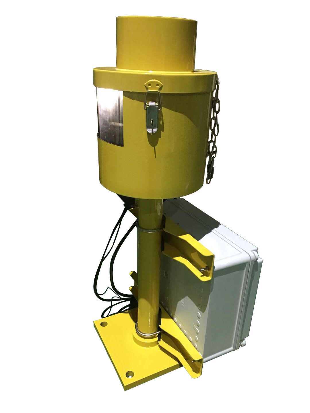
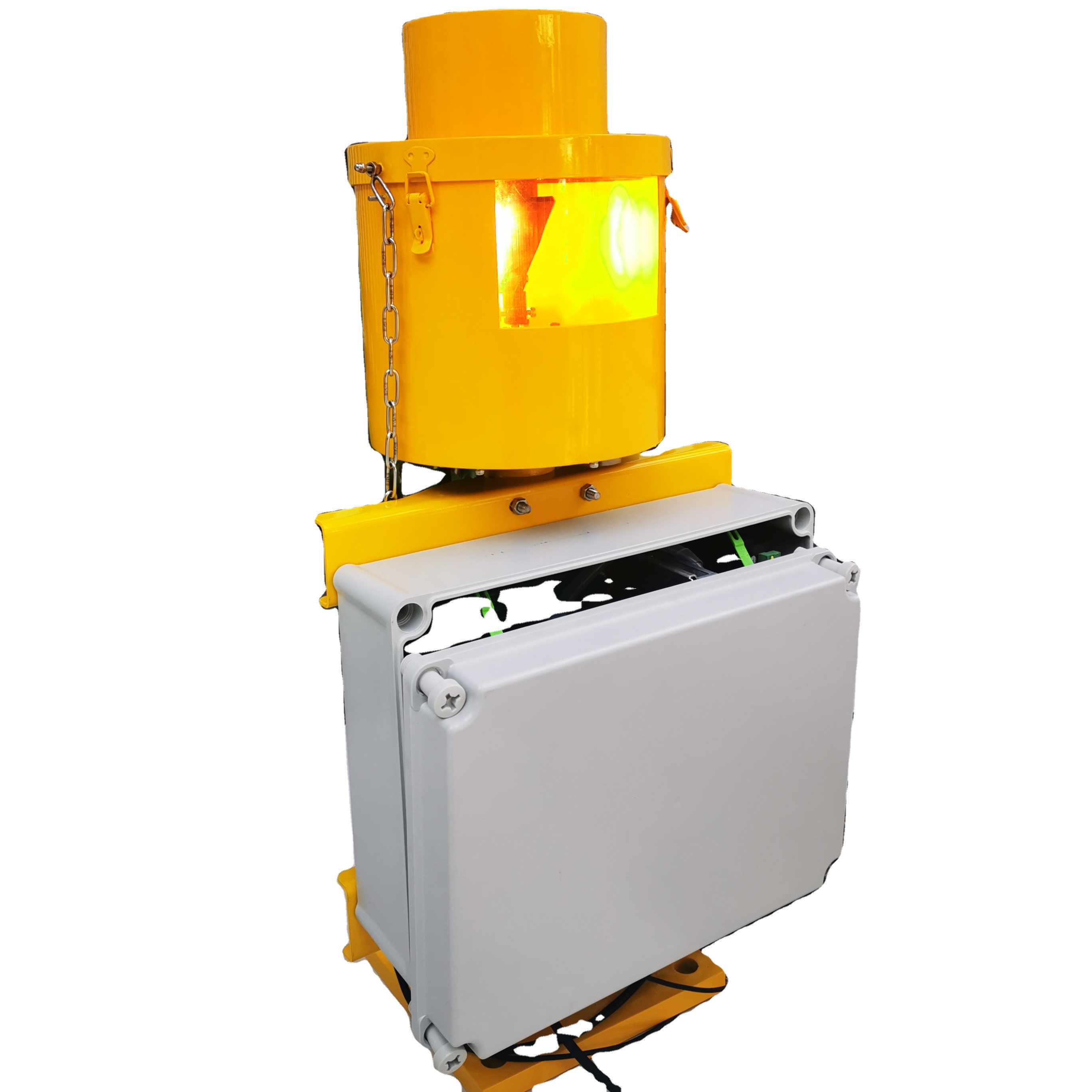
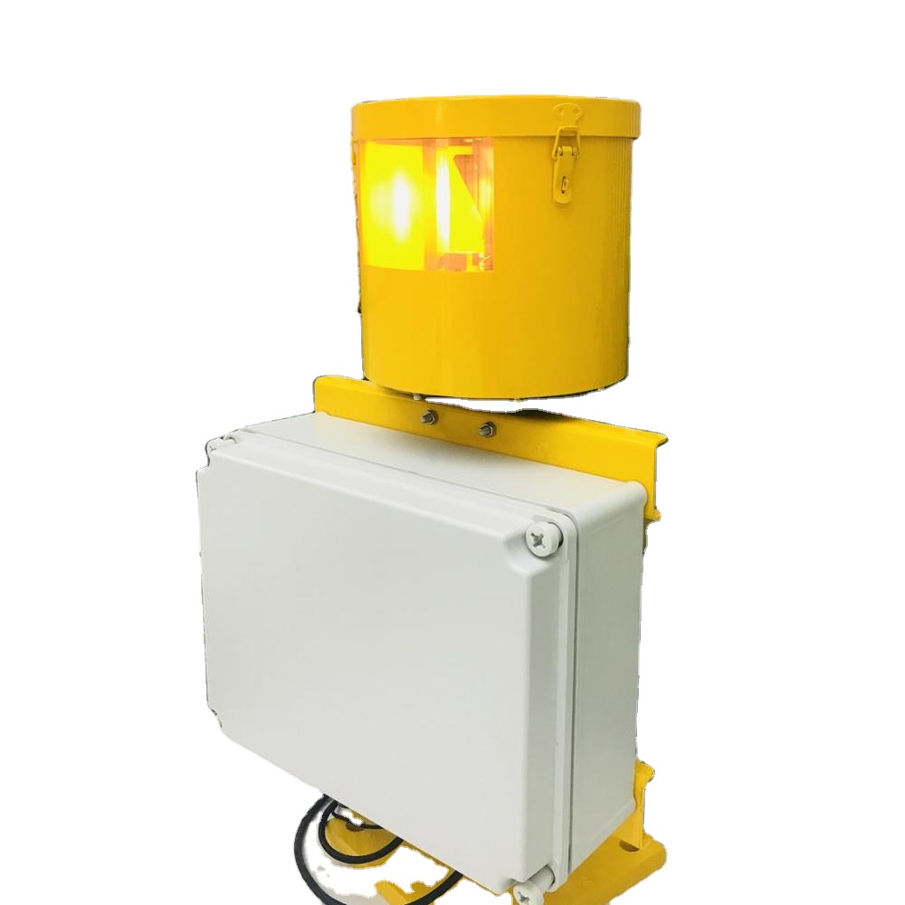
Approach Azimuth Guidance. The SAGA(System of Azimuth Guidance for Approach) provides a combined signal of approach azimuth guidance and threshold identification.
Introduction:
Approach Azimuth Guidance. The SAGA(System of Azimuth Guidance for Approach) provides a combined signal of approach azimuth guidance and threshold identification.
ICAO: Annex14 Volume II Paragraph 5.3.4
Operation Principle:
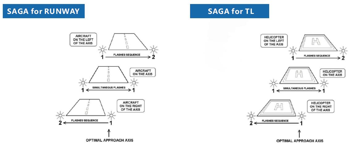
The SAGA system includes two light units (one Master and one Slave) placed symmetrically on both sides of the Runway (or TLOF) threshold supplying unidirectionalrotating beams which give a flashing effect.The pilot receives, each second illumination of two “Flashes” provided in sequence bythe two light units.
1) When the aircraft flies inside a 9° width angular sector, centred on the approach axis, the pilot sees the two lights “flashing” simultaneously.
2) When the aircraft flies inside a 30° width angular sector, centred on the approach axis and outside the previous one, the pilot sees the two lights “flashing” with a variable delay (60 to 330 ms) according to the position of the aircraft in the sector. The further the aircraft is from the axis, the greater the delay. The delay between the two “flashes” produces a sequence effect which shows the direction of the axis.
3) The visual signal is not visible when the aircraft flies outside the 30° angular sector.
Location on the field:
1. The two light units of a SAGA system must be installed at 10 metres from the runwayEdge symmetrically on both sides of the Runway threshold (for TLOF the two unitsmust be installed as close as possible to the threshold edges).
2. The Master unit must be installed on the right of the Threshold and the Slave unit on the left.

Main Advantages:
? Safe operation: The SAGA system is automatically stopped when at least one of its light units is out of service. A signal is available for monitoring of this default status in the control room.
? Easy maintenance: Very easy access to the lamp and all terminals. No special tools are required.
? Brilliancy levels: The remote control of three brilliancy levels is possible for a better visual comfort for the pilot (no dazzling).
? Efficiency: Coupled with a PAPI, the SAGA system supplies the pilot with the security and the comfort of an Optical “ILS”.
? Climate: In order to maintain operation even in very cold and/or wet areas, the light units of SAGA are equipped with heating resistors.
? Additions of red filters (option) provide to the SAGA system with the option of emitting red Flashes corresponding to fly exclusion zone due to obstacles.
Product's Specification:
| Item Name | Heliport SAGA system(System of Azimuth Guidance for Approach) |
| Model No. | CM-HT12-SAGA |
| Lamp | One 12Vac 105W pre-focused halogen reflector lamp |
| Power Supply | 110V-230Vac, 50-60Hz |
| Power Consumption | Less than 250W for the SAGA system and 240W maximum for the heating resistores |
| Visual Range | 10 nautical miles in standard visibility conditions |
| Operation Angular Sector | 15 Degrees on both side of approach axis |
| Axis Accuracy | +/- 0.45 degree in azimuth |
| Delay Between Flashes | From 60 to 300 ms |
| Flashes Frequency | 0.5Hz |
| Material | Body,cap and support are in aluminium alloy,phosphated and painted in aviation yellow.All fixing sand fastenings are stainless steel.The power supply box is made of reinforced polyester. |
| Working temperature | From -40℃ to +50℃ |
| Remote CMS | Remote control from 48Vdc.Monitoring feed back signal using two dry contacts(contact capacity=250V/1A maximum). |
| It will comprise of 2 flashing units(master and slave) located symmetrically on both sides of the runway or TLOF for heliport threshold. | |
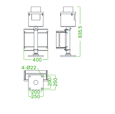
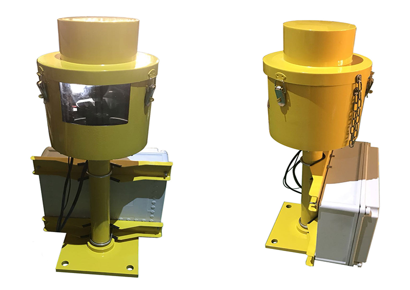
Product's Structure:
